
News

I. In DWDM transmission systems for optical fiber communications, EDFAs are generally not deployed arbitrarily; they have clearly defined roles in the transmission network and are mainly used in three key positions, as shown in the figure below:
1. Booster Amplifier (BA): Also referred to as a power amplifier or post-amplifier, it is located after the output of the optical transmitter. Since the signal power behind the optical transmitter is generally relatively high, the requirements for the noise figure and gain of the BA are not stringent, with the gain typically below 15 dB.
2. Pre-amplifier (PA): Also known as a preamplifier, it is placed before the optical receiver to amplify weak signals in advance and improve the receiving sensitivity of the optical receiver. It requires high gain and low noise, with a typical gain of around 20 dB.
3. Line Amplifier (LA): Also referred to as a line amplifier, it is deployed in the middle of the transmission line to compensate for transmission loss and extend the transmission distance. It requires low noise and high output optical power, with a typical gain of more than 25 dB.
II. Two Key Performance Indicators of EDFA
Most EDFAs used in optical fiber communications are variable gain amplifiers (VGAs), while a small number are fixed gain amplifiers (FGAs).
In addition to the key EDFA performance indicators covered in the previous chapter, several additional critical parameters are introduced here. Overall, they can be categorized into two major classes of key performance characteristics:
1. Steady-State Performance, which is mainly evaluated by these core indicators:
1): Input optical power range; Output optical power range; Gain adjustment range;
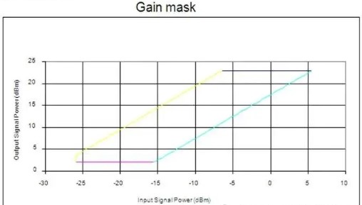
2): Gain adjustment accuracy; Gain flatness (GF)
① Without gain compensation, the gain spectrum of an Erbium-Doped Fiber Amplifier (EDFA) mainly depends on the emission and absorption cross-section spectral characteristics of the erbium-doped fiber.
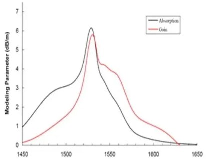
② When the length of the erbium-doped fiber is relatively short, stimulated emission dominates, and the gain spectrum of the EDFA is basically consistent with the shape of the emission spectrum of the erbium-doped fiber.
As the fiber length increases, absorption in the erbium-doped fiber begins to take effect, and the gain at shorter wavelengths increases more slowly than that at longer wavelengths.
When the erbium-doped fiber reaches a certain length, two comparable gain peaks appear in the gain spectrum around 1530–1535 nm and 1550–1560 nm respectively.
Gain compensation must be applied to address this issue.
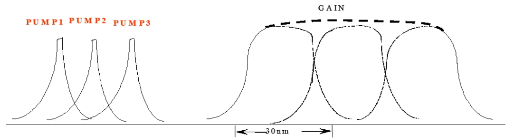
③ To achieve a flat gain spectrum, there are generally two control methods:
A) Doping with metal elements;
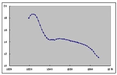
B) A gain-flattening filter (GFF), which has an anti-symmetric characteristic relative to the gain spectrum, is inserted into the EDFA. However, due to the homogeneous broadening property of erbium-doped fiber, the introduction of loss at any wavelength will cause gain variations at other wavelengths. Therefore, multiple iterative calculations are required to obtain a well-designed gain equalization filter.
The most important parameter of GFF is EF (Error of Function), which is jointly determined by the deviation between the actual loss curve of the thin film and the target loss curve (Target), as well as packaging errors. Its definition and formula are given as follows:
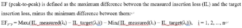
Typically, the typical value of the EF index is 0.5 dB. In most cases, the isolator and GFF can be integrated into a single device called an IGFF.
3): Noise Figure (NF) at Different Gains
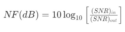
Noise Figure (NF) is the ratio of the input signal-to-noise ratio to the output signal-to-noise ratio. The formula was covered in the previous section and is given as:
Within the optical path of an EDFA, there are many factors that affect the Noise Figure (NF), including: the length of the erbium-doped fiber (Er-fiber), the pump power level, the insertion loss (IL) before the erbium-doped fiber, the amplified spontaneous emission noise (ASE) in each segment, and so on.
When a single-segment erbium-doped fiber structure cannot meet the noise requirements, a two‑segment or multi‑segment erbium-doped fiber structure must be adopted. Meanwhile, the insertion loss (IL) of components between each erbium-doped fiber segment should be evenly distributed to optimize the overall noise performance.
Examples of measured Noise Figure (NF) data are as follows:
| Gain Condition | Corresponding Noise Figure NF |
|---|---|
| Gain=28.5dB | 6.2dB |
| Gain>25.5dB | 6.6dB |
| Gain>22.5dB | 7.6dB |
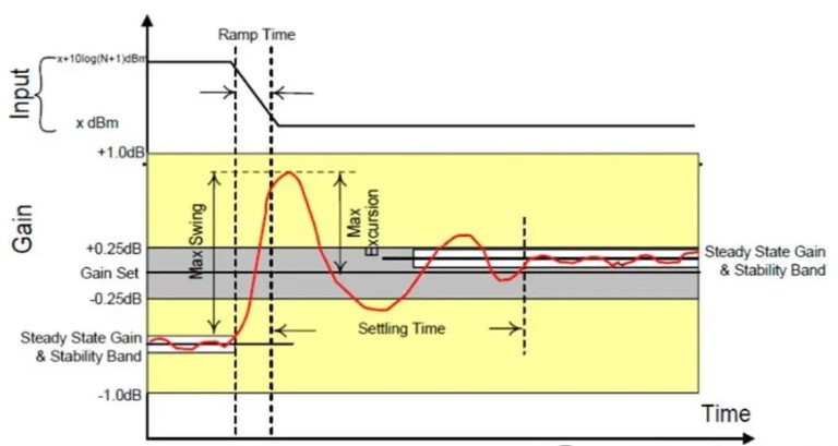
2. Transient Performance:
The main indicators of transient performance are evaluated by four parameters: Excursion, Swing, Offset, and Setting Time.
III. Brief Introduction to Two Control Modes of EDFA
1. AGC Mode
AGC is also known as gain-locked mode. Its output power varies with the input power while the gain stays unchanged, making it the most common control mode in WDM systems.
Why is AGC control required in WDM systems?
Under otherwise constant conditions, adding or dropping channels in the EDFA introduces the following problems to the system:
Therefore, gain-locking technology must be adopted for amplifiers in WDM systems.
There are multiple implementations of AGC. A common method is electrical pump power control, as described below:
By detecting the output power and input power, the actual gain is obtained. The output is adjusted by changing the pump power, so that the actual gain is finally maintained at the target gain.
The monitoring circuit controls the output of the pump source by monitoring the ratio of input power to output power.
When certain wavelengths at the input are lost and the input power decreases, the ratio of output power to input power will increase.
Through the feedback circuit, the output power of the pump source is reduced to keep the gain of the EDFA unchanged.
As a result, the total output power of the EDFA is reduced, stabilizing the output signal level.
Adopting intelligent gain control technology, the settling time is less than 10 ms. Adding or dropping channels (31 channels added/dropped in a 32-channel system) has no impact on other channels.
2. APC Mode (Automatic Power Control): Constant output power, variable gain type
Regardless of any variation in input power, the output power remains constant; the gain changes accordingly. This is the operating mode for variable gain application.
By detecting the output power and comparing it with the target output value, the pump power is adjusted to regulate the output, so that the actual output power is finally stabilized at the target output power.
Simply put: use AGC for gain stabilization, and use APC for constant output power.
IV. Extended Content of Amplifiers – Raman Amplifier
When a weak optical signal and a high-power pump light propagate simultaneously in an optical fiber, and the wavelength of the weak signal falls within the Raman gain bandwidth of the pump light, the weak signal light can be amplified. Such optical amplifier based on the stimulated Raman scattering mechanism is defined as a Raman Fiber Amplifier (RFA).
1.Three major characteristics of Raman amplifiers:
Its gain wavelength is determined by the wavelength of the pump light. As long as the wavelength of the pump source is properly selected, signal amplification at any wavelength can be achieved in theory.
Its gain medium is the transmission fiber itself, which enables the Raman fiber amplifier to amplify optical signals in-line, form distributed amplification, and realize long-distance repeater-free transmission and remote pumping.
It features a low noise figure. When used in hybrid with conventional EDFAs, it can significantly reduce the system noise figure and extend the transmission span.
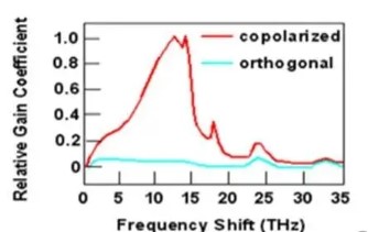
2.Principle of Raman Amplifier(Essentially an ingenious application of optical fiber nonlinear effects, which utilizes the intrinsic nonlinearity of optical fiber to realize distributed amplification.)
3.Definition of Gain in Raman Amplifier vs. Gain G in EDFA
4.EDFA vs FRA (Fiber Raman Amplifier) Comparison – Understand at a Glance
| Comparison Item | EDFA | FRA |
|---|---|---|
| Amplification Principle | Stimulated emission of erbium ions (Er³⁺) | SRS in nonlinear effect |
| Amplification Medium | Erbium-doped fiber (inside the amplifier) | Ordinary optical fiber (line fiber) |
| Pump source | 980/1480nm | Select according to the amplification target. |
| Pump Optical Power Requirement | General | High; high SRS threshold |
| Operating Bandwidth | C-band, L-band | Theoretically unlimited, determined by pump combination |
| Noise Figure | High | Low |
| Gain Test | Conventional Gain | On-off Gain |
EDFA is the basic amplification unit constituting DWDM systems, which is mainly classified into three types: pre-amplifier, power amplifier and line amplifier. It realizes system-level power stability via AGC and completes gain spectrum equalization by means of GFF.
As a distributed amplification solution, the Raman amplifier plays a key compensation role in ultra-long haul transmission and low-noise application scenarios.


