
News

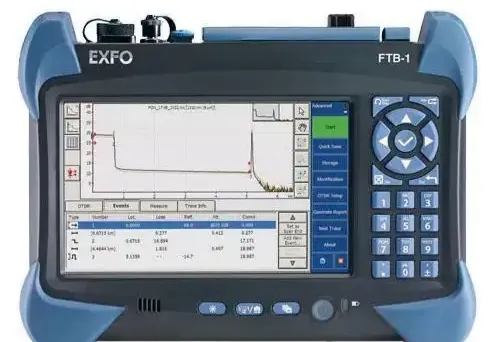
The full name of OTDR is Optical Time Domain Reflectometer, commonly known as Optical Time Domain Reflectometer. It looks roughly like this:
Fiber optic cables are widely deployed in modern communication networks. Featuring large bandwidth, low transmission loss, low latency and strong immunity to electromagnetic interference, fiber optic cables are also highly cost-effective. For these reasons, they have become the cornerstone of the modern information superhighway.
These seemingly minor anomalies can seriously affect the transmission of optical signals, causing a sharp increase in link attenuation and even leading to communication outages.
In the broadband access network, tens of thousands of households are connected via optical fibers, forming an extremely large-scale network.
These optical fibers may develop faults at any time. Without an effective detection method, troubleshooting would be like looking for a needle in a haystack. Relying on manual plugging and unplugging section by section, plus blind testing with an optical power meter, the process is time-consuming and labor-intensive, and prone to missed and misjudged faults.
In the backbone network, optical fiber links between provinces and between cities often stretch for hundreds of kilometers. As for international submarine optical cables, they span thousands of kilometers. Once a failure occurs, traditional methods cannot locate the fault quickly at all — it is impossible to inspect hundreds of kilometers of optical cables on foot along the route.
This is exactly where OTDR comes into play.
OTDR (Optical Time Domain Reflectometer) is one of the most commonly used tools for optical communication engineers, specially designed to detect faults on optical fiber lines. It is somewhat like giving the optical fiber an ultrasound and ECG examination. No matter what kind of fault occurs, OTDR can basically pinpoint the exact cause and location of the failure with high precision.
Working Principle of OTDR
The working principle of OTDR is very similar to that of radar. It emits a narrow optical pulse into the optical fiber, then "listens" to the weak reflected signal coming back. By analyzing the characteristics of the reflected signal, it can judge the internal "road condition" of the optical fiber.
More specifically, OTDR operates based on Rayleigh backscattering and Fresnel reflection.
Let’s first talk about Rayleigh scattering.
Optical fiber is made of high-purity silica glass. Although the internal atomic arrangement is highly ordered, there still exist extremely tiny density fluctuations and residual impurities. From a microscopic perspective, the fiber material is still inhomogeneous.
This causes light to scatter in all directions continuously as it propagates inside the optical fiber. It is just like shining a flashlight into fog, where faint glimmers can be seen all along the path.
A small portion of the scattered light travels back along the original path. Although this signal is very weak, it is extremely stable and continuous. Its intensity decays exponentially with distance, forming the smooth attenuation curve displayed on the OTDR screen.
This is Rayleigh scattering, which truly reflects the inherent attenuation of optical fibers.
Next, let’s talk about Fresnel reflection.
Unlike the gentle Rayleigh scattering, Fresnel reflection is an instantaneous and intense reflection. It occurs at positions with abrupt changes in refractive index, such as fiber end faces, breakpoints and connectors.
When light encounters a glass-air interface (such as an exposed breakpoint or uncleaned end face), or a boundary between two media with a large refractive index difference (such as fusion splices and movable connectors), it will generate a sharp, prominent echo peak signal, just like a flashlight shining directly onto a mirror.
Fresnel reflection truly reflects abnormal conditions of the optical fiber.
Rayleigh scattering and Fresnel reflection, one soft and one strong, work together to form the fiber “topographic map” as seen by the OTDR.
During operation, the OTDR emits high-power narrow incident optical pulses. As the pulses travel along the line, they generate Rayleigh scattered light and Fresnel reflected light all along the fiber route.
These backscattered lights are captured by the high-sensitivity receiver of the OTDR. After photoelectric conversion and signal processing, a power attenuation curve varying with distance is formed — namely the OTDR trace.
On the OTDR trace, the horizontal axis represents fiber length, and the vertical axis represents echo power. Abnormal positions such as breakpoints, fusion splices and bending points appear as obvious steps, sharp peaks or abrupt slope changes on the curve.
Combining the speed of light and the round-trip time of the pulse, the OTDR can accurately calculate the distance from the test end to the fault point, with a typical error of less than 1 meter.
How to Use an OTDR
The core operating procedure of an OTDR consists of seven steps: Preparation → Cleaning → Connection → Parameter Setting → Testing → Analysis → Saving.
During operation, three major principles must be strictly followed: laser safety, end-face cleaning, and parameter matching.
Step 1: Preparation
Mainly check the condition of the device: inspect whether there is any damage to the appearance, and confirm that the battery level is sufficient (≥30%) or the device is connected to a power supply.
Step 2: Cleaning
Dip a dust-free cotton swab in 99% anhydrous alcohol, and wipe the OTDR optical port in one direction, then replace the dust cap immediately.
Note: The end face of the patch cord shall also be inspected with an alcohol cotton swab and an end face microscope (end face inspector). It is qualified only when completely free of dust and contamination.
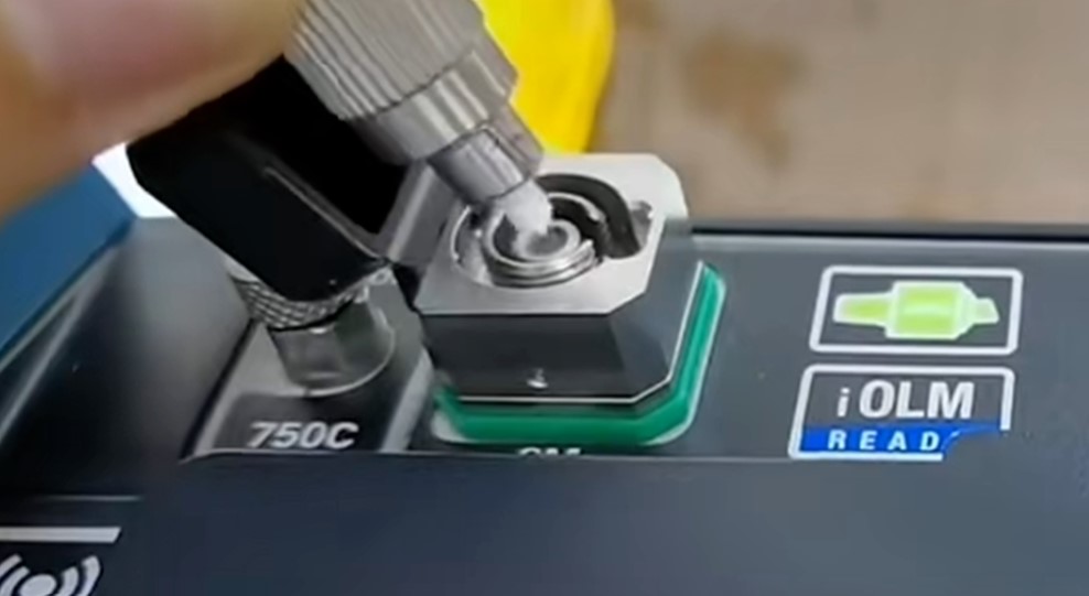
Step 3: Connection
Connect the test port of the OTDR to the starting end of the fiber under test via a patch cord, and ensure the buckle is securely locked.
Connect the other end of the test patch cord to the fiber under test through an adapter flange. Insert and rotate gently to avoid lateral force that may damage the fragile ceramic ferrule.
Note: All active devices (such as switches and OLTs) at both ends of the fiber under test must be disconnected to prevent reflected light from damaging the OTDR.
In addition, never look directly into the OTDR optical port or fiber end face when the device is powered on. Laser radiation can cause permanent blindness — this is no joke.
Normally, an anti-static wristband must be worn when using an OTDR to prevent static electricity from damaging the equipment.
This step is critical. Improper parameter configuration will fail to deliver optimal test results.
Like many other instruments, OTDR follows the principle of coarse adjustment first, then fine adjustment to gradually improve testing accuracy.
You may first select Auto Mode (one-click start with automatic parameter matching by the instrument) to quickly generate a trace, then switch to Manual Mode to fine-tune pulse width, averaging time and range for targeted optimization.
Set parameters such as pulse width (narrow pulse for near-end details, wide pulse for long-distance testing), wavelength (1310nm/1550nm/1625nm), and averaging time (longer time brings higher signal-to-noise ratio and smoother curve) according to fiber type (single-mode / multi-mode), estimated fiber length and accuracy requirements.
For measurement range, it is generally set to 1.5 to 2 times the actual fiber length to avoid false end reflection peaks.
Press the test key and wait for several seconds to tens of seconds.
The OTDR trace that reflects the health status of the entire fiber link will be displayed on the screen.
It is just like an ECG of the optical fiber; every fluctuation on the curve corresponds to the loss and abnormalities encountered by optical signals propagating in the fiber core.
Once the trace is obtained, conduct an in-depth analysis to identify the specific status and faults of the optical fiber link.
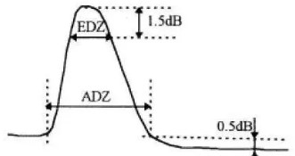
There is another key concept of OTDR — dead zone.
The dead zone refers to a certain distance segment right after a strong reflection event (such as a connector end face). Due to the temporary "blindness" of the OTDR receiver, it cannot accurately identify weak adjacent events within this range.
It is just like the human eye turning from strong light to look into a dark place and experiencing temporary blurred vision. This is not a fault of the instrument, but a physical limitation.
Dead zones are divided into two categories: Event Dead Zone (EDZ) (typically 1–5 meters, affecting the identification of near-end connectors) and Attenuation Dead Zone (ADZ) (approximately 10–20 meters, affecting the accuracy of loss measurement).
In practical operation, selecting a short pulse width and high-resolution mode can narrow down the dead zone. Meanwhile, using an OTDR with a pigtail or adopting the loopback test method can effectively avoid the blind spot of the dead zone.
Step 7: Data Saving
The OTDR can save the measured trace curves. They are usually stored in standard file formats such as .sor or .trc, with key information annotated including test time, location, fiber ID, wavelength, and operator.
Conclusion
The accuracy of OTDR testing depends 70% on cleaning and connection, 20% on parameter configuration, and 10% on curve interpretation.
Strictly following the standard workflow — clean first, then connect; auto mode first, then fine tuning; bidirectional testing, and save the trace — is the fundamental guarantee for obtaining reliable test data and accurately locating fiber faults.
At present, optical fiber communication will remain the dominant wired communication medium for mankind in the coming decades. It will be widely deployed in key scenarios such as base station backhaul, broadband home access, and data centers.
As for OTDR, it serves as the most effective tool to safeguard this optical infrastructure network.
Proficiency in operating an OTDR is a basic essential skill for every optical communication engineer.


