

Knowledge Center
Technology Insights · Industry Trends · Product Knowledge · Application Notes · News & Updates

No matter how fast light travels inside optical fiber, it cannot escape a fundamental physical rule: optical power attenuates over distance. Standard single-mode fiber exhibits low loss around the 1550 nm window, yet low loss does not equal zero loss. After several tens of kilometers, optical signals gradually degrade due to fiber attenuation, connectors, fusion splices, MUX/DEMUX components and ROADM nodes.
The intuitive workaround is optical-electrical-optical (O-E-O) regeneration: convert light into electricity, perform signal decision and reshaping, then retransmit a new optical signal. However, for DWDM links carrying dozens or even hundreds of wavelengths simultaneously, dedicated O-E-O regeneration per wavelength leads to extremely complex hardware. This is where EDFA delivers its core value: it does not interpret digital 0s and 1s, nor convert light into electrical signals. Instead, a full set of optical signals near 1550 nm pass through a specialized fiber and get amplified collectively.
Follow “光芯片 home” Continuous deep dives into optical chip principles, component specifications and industry trends
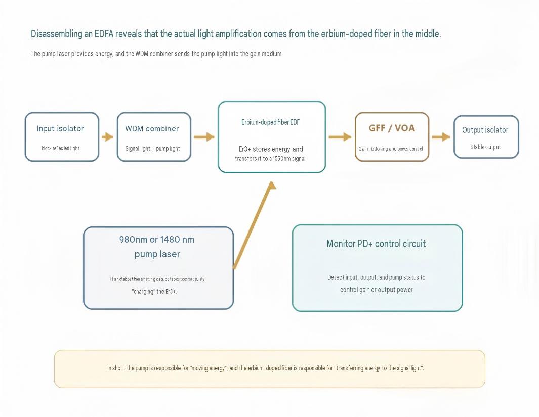
EDFA stands for Erbium-Doped Fiber Amplifier. Its architecture includes pump lasers, WDM multiplexers, erbium-doped fiber, optical isolators, filters, monitoring photodiodes and control circuits. The actual optical gain medium is the fiber core doped with trivalent erbium ions (Er³⁺).
It amplifies the optical field directly rather than recovering individual bits After entering an EDFA, the signal retains its original wavelength, modulation format and line rate. The amplifier is agnostic to whether the traffic is 10G, 100G or 800G, and regardless of NRZ, PAM4, QPSK or 16QAM modulation. Optical gain is provided as long as the signal falls within the effective gain bandwidth.
This grants EDFA two key characteristics: protocol transparency and simultaneous multi-wavelength amplification. DWDM systems avoid deploying discrete electrical regenerators for each channel; one EDFA can boost the power of the entire wavelength comb. For this reason, EDFA has become foundational infrastructure for long-haul transmission, metro networks, submarine cables, DCI and open optical line systems.
Important note: EDFA only compensates optical power. It cannot restore a closed eye diagram, eliminate chromatic dispersion, correct bit errors or recover degraded OSNR.
Inject pump energy, generate optical signal gain, stabilize system performance
Pump Laser: “Charging” erbium ionsCommon EDFA implementations use 980 nm or 1480 nm pump lasers. Pump light carries no service payload; its purpose is to deliver energy into erbium-doped fiber, lifting large quantities of Er³⁺ from the ground state to higher energy levels and creating conditions for stimulated emission.
WDM Multiplexer: Combine pump light and signal light within one fiber corePump wavelengths differ from the 1550 nm-band service signals. A WDM combiner merges both lightwaves into the same erbium-doped fiber with low insertion loss. Pump configurations include co-propagation, counter-propagation and bidirectional pumping.
Erbium-Doped Fiber: The physical medium where optical gain occursStandard silica fiber transports light, while erbium-doped fiber incorporates trace Er³⁺ dopants within the core. After absorbing pump energy, these ions transition to excited states. When illuminated by signal photons of the correct wavelength, stimulated emission releases additional identical photons. As signals propagate through several meters to tens of meters of gain fiber, optical power accumulates continuously.
Isolator, GFF, VOA and Monitoring Circuits: Ensure practical amplifier operationOptical isolators suppress back-reflected light and parasitic oscillation. Gain Flattening Filters (GFF) mitigate wavelength-dependent gain imbalance. Variable Optical Attenuators (VOA) regulate gain or output power. Monitoring photodiodes and control circuitry track input power, output power and pump status in real time, supporting constant-gain, constant-output and transient power control modes.
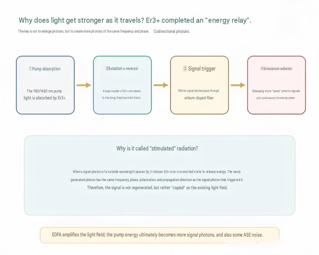
Three sequential steps create optical gain: pump absorption, population inversion, stimulated emission To simplify the principle, Er³⁺ ions can be visualized as tiny energy storage nodes. Pump laser energy excites ions from the ground state to high-energy levels. For 980 nm pumping, ions first reach an upper level before rapid non-radiative relaxation into a long-lived metastable state. When enough ions occupy the metastable state, population inversion is achieved.
When a ~1550 nm signal photon passes by, it triggers an excited Er³⁺ ion to drop to a lower energy level and emit a new photon. This new photon matches the incident signal photon in frequency, phase, polarization and propagation direction, coherently reinforcing the original optical signal. Repeating this process amplifies optical power along the doped fiber.
Not all excited ions await stimulation by signal photons. Some release random photons spontaneously; these spontaneous photons are further amplified by the gain medium, producing ASE (Amplified Spontaneous Emission). ASE constitutes the primary noise source in EDFAs and limits the maximum number of cascaded amplifiers in long fiber links.
A perfect alignment between material energy levels and optical communication bands Silica fiber exhibits minimal transmission loss near 1550 nm, and specific energy-level transitions of Er³⁺ within glass host materials precisely cover this communication window. Erbium-doped fiber retains the advantages of standard fiber: low intrinsic loss, easy fusion splicing and long light-matter interaction length, while adding pump-activated optical gain.
Conventional EDFA primarily supports the C-band, typically 1530–1565 nm in engineering deployments. Adjustments to doping concentration, fiber length and pumping architecture enable L-band amplification. Extended C-band, Super C and C+L systems require sophisticated gain equalization, cascading and dual-band amplifier designs.
Both wavelengths work, differing in energy transition paths, efficiency and noise tradeoffs
980 nm pumping: Ions populate an upper level before relaxing to the metastable state 980 nm pumping generally delivers superior noise performance, making it ideal for pre-amplifiers. Mature 980 nm pump lasers, couplers and control schemes make this the most widespread option.
1480 nm pumping: Excites ions directly near the metastable level 1480 nm sits closer to the signal band with lower quantum defect, offering advantages for high-power, high-efficiency designs and commonly used for counter or bidirectional pumping. However, it shares energy levels closer to service wavelengths, requiring careful tradeoff analysis for noise, pump utilization and gain distribution.
Neither wavelength is universally superior. Low-noise preamps, high-power booster amplifiers and wide dynamic-range in-line amplifiers may adopt different pump wavelengths, propagation directions and multi-stage architectures. High-performance products often deploy multiple pump laser diodes.
Gain, saturated output power, noise figure and gain flatness must be evaluated collectively
Gain (G): Magnitude of signal amplification Expressed in decibels: G = Pout − Pin (when power values use dBm). 20 dB gain corresponds to a 100× power increase; 30 dB equals 1000× amplification. Higher gain is not always desirable: links require only enough compensation to offset fiber loss while preserving OSNR and nonlinear power budgets.
Saturated Output Power: Maximum deliverable optical power As input signal power or channel count rises, stored energy within Er³⁺ depletes faster, causing gain compression and output saturation. Booster amplifiers prioritize saturated output power. For multi-channel systems, total output power is shared across wavelengths; total dBm values cannot be misinterpreted as per-channel power.
Noise Figure (NF): OSNR degradation introduced by amplification An ideal amplifier boosts signals without adding noise, while practical EDFAs introduce ASE. A lower noise figure means less signal-to-noise degradation. Pre-amplifiers before receivers are highly sensitive to NF; cascaded EDFAs accumulate noise segment by segment.
Gain Flatness, Tilt and Ripple: Uniform amplification across wavelengths The native gain spectrum of Er³⁺ is uneven. Without GFF or dynamic equalization, DWDM channels develop large power discrepancies after traversing multiple amplification sites. Gain flatness, gain tilt and ripple determine whether all wavelengths maintain balanced power levels.
Input Power Range & Control Modes: Long-term network stability Datasheets also specify acceptable input power window, adjustable gain range, constant-gain / constant-output operation, transient response, pump redundancy, return loss, PMD and monitoring interfaces. When ROADM nodes add or drop wavelengths dynamically, total input power fluctuates; control loops must suppress power overshoot on remaining active channels.
Optimal performance targets vary by location
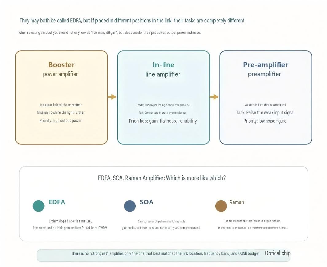
Booster Amplifier: Deployed at the transmitter egressMUX and WSS components introduce insertion loss. Booster amplifiers after transceivers deliver high total output power to provide sufficient link budget for long-distance fiber transmission. Key metrics include saturated output power and reliability, while per-channel power must be capped to avoid fiber nonlinearities.
In-Line Amplifier: Mid-span loss compensationInstalled between network nodes to periodically restore power lost in fiber and optical nodes. In-line EDFAs must maintain stable gain, flatness and transient behavior during unattended operation, commonly paired with OCM, OSC, VOA or dynamic gain equalizers.
Pre-Amplifier: Deployed immediately before the receiverPre-amplifiers process weak incoming optical signals, prioritizing low noise figure and adequate gain. They elevate both the signal and ASE for receiver processing. If upstream OSNR has already degraded severely, pre-amplification amplifies signal and noise equally and cannot recover lost signal quality.
Every amplification stage consumes OSNR and may exacerbate power imbalance
ASE accumulation: Each EDFA generates new ASE noise, and subsequent amplifiers further amplify noise from preceding stages. More cascaded units degrade OSNR progressively. Receivers may detect adequate total optical power yet fail correct bit decision.
Accumulated gain imbalance: A 0.2 dB per-site wavelength gain difference creates significant power divergence after a dozen amplification nodes. Overpowered channels saturate gain media and trigger fiber nonlinear effects.
EDFA does not compensate waveform distortion: Pulse broadening from dispersion, nonlinear distortion or filtering-induced narrowing persists; EDFA amplifies the degraded optical field without reshaping. True 3R regeneration requires re-timing, reshaping and retransmission.
Selection depends on gain medium and system priorities
EDFA: Dominant solution for C/L-band long-haul transmissionGain medium: erbium-doped fiber. Strengths include native fiber compatibility, high gain, low polarization sensitivity, favorable noise performance and simultaneous multi-channel DWDM amplification. Limitations: gain restricted to erbium bandwidth, larger footprint compared with chip-scale amplifiers.
SOA (Semiconductor Optical Amplifier): Chip-integrated gainSOAs use semiconductor active regions for optical amplification, featuring compact size, fast response and ease of PIC integration. They also support optical switching and wavelength conversion. Drawbacks include pronounced gain saturation, crosstalk, polarization dependence and inferior noise performance versus high-grade EDFAs.
Raman Amplifier: Distributed gain within transmission fiberDistributed Raman amplification uses high-power pump light to stimulate Raman scattering inside the transmission fiber, delivering gain as signals propagate. It improves effective noise performance and extends span reach; gain bands can be customized via pump wavelengths. Tradeoffs include high pump power requirements, optical safety constraints and complex system control. Hybrid EDFA+Raman architectures are widely adopted in engineering practice.
Do not confuse increased optical power with restored signal quality
❌ Misconception: EDFA repairs degraded signals. It only compensates power; dispersion, nonlinear distortion, filtering impairments and pre-existing bit errors remain unresolved.
❌ Misconception: Higher output power guarantees longer transmission reach. Excessive per-channel power intensifies nonlinear effects such as SPM, XPM and FWM.
❌ Misconception: 30 dB gain is inherently superior to 20 dB. Gain must match span loss, input dynamic range, NF, saturation output and channel power budgets.
❌ Misconception: EDFA amplifies all wavelengths equally. Operation is limited to erbium’s effective gain band, and native gain varies by wavelength.
❌ Misconception: A single EDFA supports unlimited DWDM channels. Total output power is finite; additional channels share available power and introduce gain competition and transient fluctuations.
It cannot interpret data, yet defines maximum transmission reach When signal light enters an EDFA, it avoids O-E conversion and re-encoding. Pump laser energy is temporarily stored within Er³⁺ ions; 1550 nm signal photons extract this stored energy via stimulated emission, generating additional coherent identical photons.
Core takeaway: EDFA does not “magnify” original photons. It uses pump energy to replicate photons with identical frequency, phase and propagation direction.
EDFA enables simultaneous amplification for full DWDM wavelength combos and drastically simplifies long-distance optical networking. Nevertheless, it introduces ASE, gain compression and inter-channel power tilt. A well-designed EDFA balances output power, noise figure, gain flatness, dynamic range and transient control rather than pursuing maximum raw gain.
Remember: Restored optical power ≠ regenerated signal quality. EDFA is an optical power repeater, not a 3R regenerator.
Standard optical communication terminology strictly follows international technical documents: EDFA, ASE, OSNR, NF, GFF, VOA, SPM, XPM, FWM, 3R regeneration, O-E-O
Preserved the original popular-science narrative flow, analogy explanation and full article structure, suitable for overseas technical blogs, whitepapers and pre-sales material
Physical principle descriptions maintain scientific rigor while avoiding overly obscure academic phrasing
Consistent glossary aligned with previous bilingual articles (800G optical module, Modular WDM) for your full technical document library
If needed, I can compile EDFA + 800G Module Selection + Modular WDM + 800G Disassembly into a complete Chinese-English optical transmission knowledge package.

APEX GROUP LIMITED
Phone: 85298213834
WhatsApp: 85298213834
Email: Info@apexallinone.com


