

Communication Products
Optical Transceivers · Telecom Synchronization · Network Infrastructure · Custom Solutions
A radio site terminates its fronthaul links locally and sends the aggregated traffic back towards the core. That is the backhaul; in dense areas the same span also carries mid-haul traffic between distributed and centralised units. One aggregation node can collect dozens of radio sites, so the backhaul port carries the sum of them on one link, normally in a ring so that a single cut does not isolate a site.
100G is the working rate for that link. 25G sits at the site edge and on the fronthaul ports, 100G aggregates a group of sites, and 400G sits at the top of the hierarchy. Choosing the 100G optic is mostly a span question - distance, loss, fibre count, whether a line system exists - and only secondarily a question about the module.
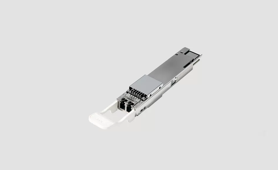
QSFP28 delivers 100G in a cage long enough in service to be well understood, with several interface types behind the same footprint: SR4 and CWDM4 for short campus and aggregation runs, PSM4 for parallel-fibre sites, LR4 for a standard 10 km span, ER4 for a longer one, and a coherent ZR part where an amplified design makes more sense than an extra regenerator. The same port can break out to four 25G links where the far end is a group of radio sites rather than one node.
| Module | Rate | Media / wavelength | Reach | Typical use |
|---|---|---|---|---|
| 100G QSFP28 SR4 | 100G | MMF, 850 nm parallel | 70 to 100 m | Within a hub or shelter, patching between aggregation frames |
| 100G QSFP28 CWDM4 | 100G | SMF, CWDM 1271 to 1331 nm | 2 km | Campus and short metro runs between aggregation sites |
| 100G QSFP28 PSM4 | 100G | SMF, 1310 nm parallel | 500 m to 2 km | Parallel-fibre plants and short runs to a data hall |
| 100G QSFP28 LR4 | 100G | SMF, LAN-WDM 1295 to 1310 nm | 10 km | Standard backhaul span in a metro ring |
| 100G QSFP28 ER4 | 100G | SMF, LAN-WDM | 30 to 40 km | Longer backhaul span or sparse site layout |
| 100G QSFP28 ZR | 100G coherent | DWDM C-band, tunable | 80 km class and beyond with amplification | Amplified backhaul, DWDM ring, muxponder uplink |
| 100G QSFP28 BiDi | 100G | SMF, single-fibre wavelength pair | 10 to 20 km | Fibre-poor sites where only one strand is free |
| 100G to 4x25G breakout | 100G host, 4x25G links | SMF or MMF plus breakout assembly | Span dependent | Splitting an aggregate port towards four radio sites |
Reach figures are the standard classes for each interface type; the working limit is the loss budget. The full set of form factors and distances is on the 100G QSFP28 transceiver page, and the site-edge ports that feed this link are covered by the 25G SFP28 family.
Backhaul rings are usually built on fibre that is already there. Three answers are common. On dark fibre, one LR4 or ER4 pair per 100G link is the simplest design and scales by adding pairs. On CWDM or DWDM with passive muxes, several 100G links share one fibre pair, which is what most metro rings use once the pair count runs out. For long amplified spans, a coherent 100G ZR channel on the DWDM grid carries traffic further without a regenerator. Decide this first: it sets the wavelength plan the modules are ordered against.
Backhaul and mid-haul links carry PTP and SyncE alongside the user plane, and the optical layer passes that timing without adding jitter. Two practical points follow. Latency and FEC class should be consistent along a chain, because mixing generations on one path changes the delay budget and complicates fault-finding. And on a link close to its reach limit, a longer-reach module beats an extra amplifier, since every added element adds delay and a failure point.
Aggregation cabinets and pole-mounted equipment see the full outdoor range, and the module inside is often the first component to drift. Commercial grade optics rated for a conditioned room are a common cause of a link that works at commissioning and flaps in midsummer. Specify the industrial grade for anything outside a cooled shelter, state it in the RFQ so it is not substituted, and keep the grade consistent around a ring so the fault pattern stays predictable.
The module has to be coded for the host you name, and a breakout assembly has to match the host's port configuration where a 100G port is split into four 25G links. Modules supplied for branded platforms are compatible parts and are not manufactured by the brand of the host, with no claim of relationship to that brand. Name the platform model and port type in the order, and note whether the link has to interoperate with optics already in service at the far end. Vendors seen in this layer include Cisco, Nokia, Huawei and ZTE platforms, among others.
Is 100G enough for 5G backhaul?
For aggregating a group of radio sites it is the working rate today, with 400G at the upper layers. Where one span carries an unusually large cluster, plan the 400G upgrade for that span.
LR4 or ER4 for a 25 km span?
ER4 is the usual choice. LR4 is specified to the 10 km class, and running beyond that spends margin that should be kept for ageing and repairs.
When is a coherent 100G ZR module the better answer?
On amplified spans and DWDM rings, and on long links where a regenerator or amplifier site would otherwise be needed. On a short unamplified span, LR4 or ER4 is simpler and cheaper.
Do the backhaul optics have to pass PTP and SyncE?
Yes, and the optical layer passes timing without adding jitter. Keep latency and FEC class consistent along the chain, and confirm the requirement with the transport and RAN vendors.
Can one 100G port feed four radio sites?
Yes, with a breakout to four 25G links where the host port supports it and the far ends are 25G. Confirm the breakout assembly and host configuration together, since coding and port mapping both have to match.
Send the span distance, the measured loss, the host platform and the number of sites behind the link, and we confirm the interface type, temperature grade and coding before shipment. Related reading: WDM transceivers for the CWDM and DWDM options, 400G QSFP-DD and OSFP optics for the layer above, and all optics selection guides.
APEX is a communication technology brand focused on optical transceivers, telecom synchronization products, and network infrastructure equipment. We provide products and engineering support for telecom operators, data centers, mobile networks, and enterprise customers worldwide.
APEX GROUP is headquartered in Hong Kong, with our core team and supply chain operations based in China. We ship to customers across Asia, the Middle East, Europe, Africa, and the Americas.
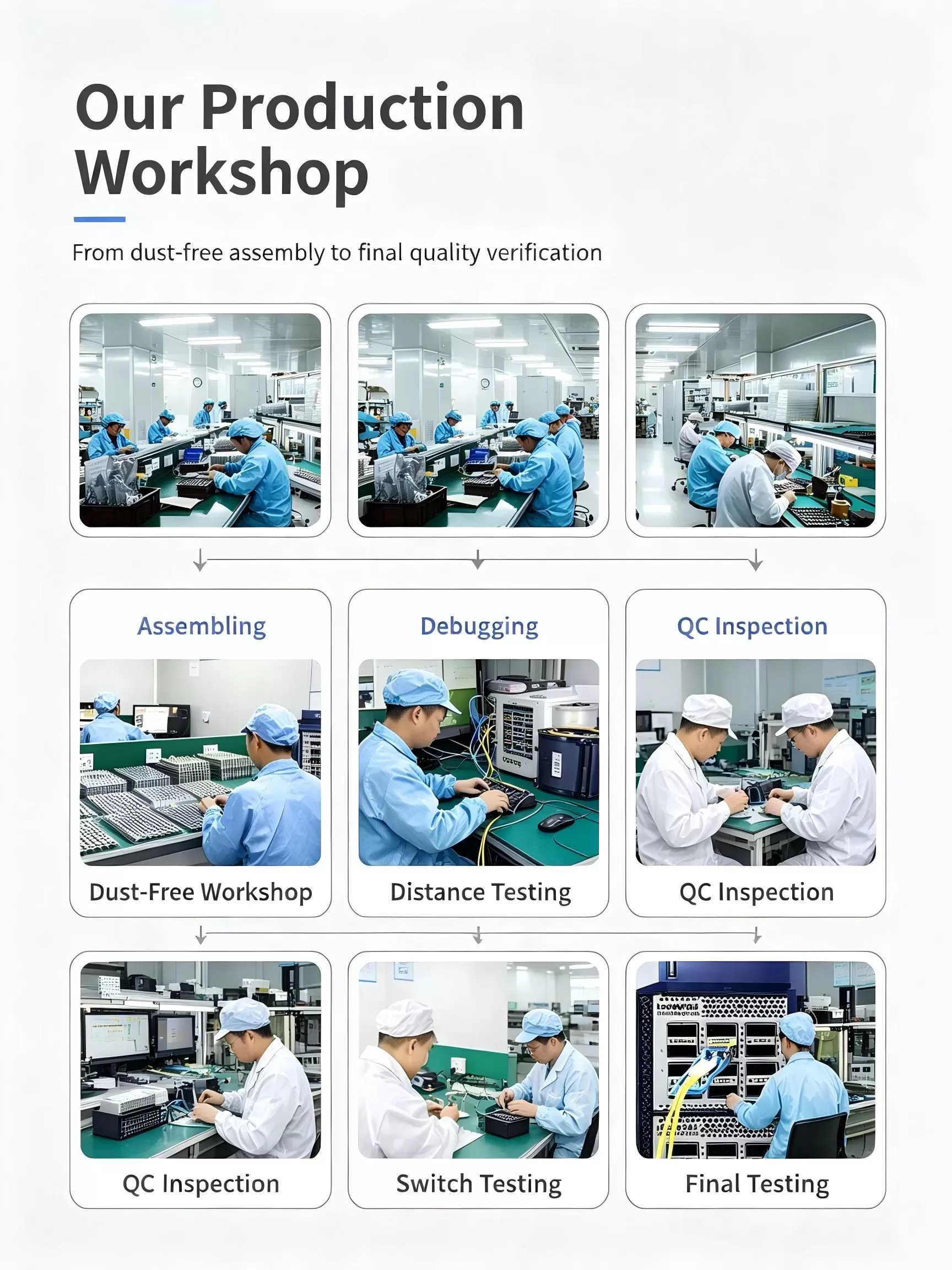
We are a brand owner with deep engineering partnerships. We control product design, specification, quality validation, and supply chain management. Our products are built to our specifications by qualified manufacturing partners, and we handle all testing, coding, and quality assurance before shipment.
Yes. We code transceivers to match the host platform requirements of major switch and router vendors including Cisco, Juniper, Arista, HPE, Huawei, Nokia, and others. Tell us your platform model and required OS version, and we will ship modules that are recognized natively by your equipment.
Datasheets, compatibility matrices, and S-parameter reports are available for all standard products. Contact our sales team or visit the product pages on our website to request documentation.
Provide us with your switch make, model, and OS version. We code the transceiver firmware accordingly before shipment. If you are testing for the first time, we recommend ordering a sample unit to validate compatibility in your specific environment before placing a volume order.
Switch vendors occasionally introduce transceiver whitelisting in new OS releases. We track major platform updates and can provide recoded firmware matching the new OS requirements. Contact technical support if your existing APEX modules stop being recognized after a switch upgrade.
Contact our sales team by email, WhatsApp, or WeChat with your part number and quantity. We will confirm pricing, lead time, and shipping options. For first-time customers, we typically recommend starting with a sample order to validate compatibility before scaling to production volumes.
We ship via DHL, FedEx, and UPS for express delivery, typically 3-7 business days to most destinations. For volume orders, we also offer air freight and sea freight options. We can ship on your courier account or ours, and we handle all export documentation.
Sample orders start from 1-2 units for evaluation. For production orders, MOQ varies by product type, typically 10-50 units for standard transceivers. Contact us for specific product MOQs.
We accept wire transfer (T/T) as our standard payment method. For established customers, we can offer net-term payment arrangements. Contact our sales team to discuss payment terms.
All APEX products come with a 3-year standard warranty against manufacturing defects. We offer advance replacement for defective units, shipping the replacement before you return the failed unit to minimize downtime. For full details, visit our After-Sales Service page.
Contact us by email, WhatsApp, or WeChat. Describe your issue with as much detail as possible, including switch model, OS version, transceiver part number, and the problem you are seeing. Our support engineers will respond within one business day.
Yes, we strongly encourage sample testing. Order 1-2 units of each model you plan to deploy. Test them in your switches with your fiber plant and traffic load. Once validated, we can proceed with production quantities.
Yes. Many of our customers are telecom operators and government networks requiring 5-10 year supply continuity. We offer lifecycle management commitments with advance notification of any changes. See our Global Supply Chain page for details on long-term supply programs.

APEX GROUP LIMITED
Phone: 85298213834
WhatsApp: 85298213834
Email: Info@apexallinone.com


