

Communication Products
Optical Transceivers · Telecom Synchronization · Network Infrastructure · Custom Solutions
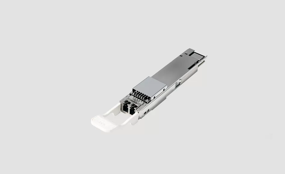
Terrestrial long haul and submarine links share one property: the distance is large enough that the optical signal has to be managed rather than simply transported. Both use coherent detection, both plan the link as a chain of spans with amplifiers, and both stand or fall on the loss budget of the buried or submerged plant rather than on the module alone.
The difference is the cost of change. A terrestrial span can be reworked in days, while a submarine segment may not be touched for years, so planning margin and the sparing strategy carry more weight than the price of the optics. This guide covers the module and line card side of those links. The transport layer is described on the OTN and DWDM transport platform page, and the rate families are on optics selection guides.
Direct detect links tolerate dispersion and attenuation and stop working when either grows. Coherent detection reads the phase as well as the amplitude of the light, so the receiver can compensate for dispersion and polarisation effects electrically instead of optically. That is what allows a single carrier to close over a chain of amplified spans, and it is why long routes are planned in coherent modes with strong error correction rather than in grey rates.
It also changes the question. The useful enquiry is not which module reaches furthest, but which mode list closes on the measured chain with margin. Reach on a long route is a computed property of the chain, because span loss, amplifier spacing, channel count and the mode in use all move the number.
| Module or card | Rate | Media / wavelength | Reach class | Where it usually lands |
|---|---|---|---|---|
| 100G coherent line module | 100G | SMF, C band tunable | Metro to long haul classes | Routes where 100G still fills the fibre |
| 400G coherent line module | 400G | SMF, C band tunable | Regional to long haul classes | Regional transport and long span data center links |
| 800G coherent line module | 800G | SMF, C band tunable | Metro to regional classes | New capacity on an existing line system |
| 400G ZR and ZR+ pluggables | 400G | SMF, C band tunable | Metro to regional classes | Router ports where no shelf is wanted |
| Transponder and muxponder cards | 100G to 800G | Client side per service | Per card and mode | Mapping grey clients into long span wavelengths |
| C band and extended band line systems | Per channel | SMF, C band and beyond | Per span class | Amplified chains with many channels |
Reach is a computed property of the chain rather than a figure on a data sheet. The coherent modules themselves are compared on coherent optics and the card route on 800G DCO transponder cards.
A repeatered link has amplifier sites along it, which makes gain, gain flatness and loss per span the working variables. An unrepeatered link has no site in the water or in the duct, so everything is spent at the terminals: higher launch power, remote amplification and a stronger code. Unrepeatered routes are usually shorter and cost more per kilometre at the terminals, and in exchange they avoid the cost and the risk of a submerged site. Settle early where the amplifier sites are, because that single fact decides the mode list and the launch power targets.
Long routes are planned in the C band first because standard amplifiers work there, and above it when the C band is full and the fibre cannot be changed. Adding capacity that way is a terminal and amplifier change rather than a cable change, which is why it is the usual way to grow a route that cannot be re-cabled. Channel plans belong in the request: the grid, the occupied channels, the target channel, and the number of channels the line can carry now and later. Line systems and passive modules for those plans are described on the DWDM line system expansion and DWDM mux and demux module pages.
Where access is expensive, sparing changes shape. A pluggable or a card can be replaced by a technician in minutes, while an amplifier in a submerged housing cannot. That is why long routes hold spares at the terminals by link family, and why a tunable part is preferred over a fixed channel module: one tunable spare covers every channel in the band. The terminal record should say which mode and channel each working part was set to, because a spare that needs a plan change is a spare in name only.
Where a module sits in a router or a switch cage it is coded for the host named on the request, tested on that model, and it is not manufactured by that brand. Parts for the common hosts are collected on the Cisco, Nokia and Juniper pages. Line cards in a transport shelf follow the compatibility list of that shelf instead.
Is submarine equipment different from terrestrial long haul equipment?
The modules and cards belong to the same families. What differs is the planning margin, the sparing plan and the fact that a submerged amplifier cannot simply be replaced in service.
Can a long route be built without coherent optics?
Not at these distances. Direct detect rates are used at the terminals for short client connections and stop well short of an amplified chain.
Which band should be used first?
The C band, because standard amplifiers work there. Move above it when the C band is full and the fibre itself cannot be changed.
How should spares be planned for a long route?
One tunable part per link family at each terminal, with the same mode list as the working part, and the mode and channel of each unit recorded with the terminal.
What do you need to quote a long haul or submarine project?
The span list with measured losses and amplifier positions, the client service list, the line rate and mode list, the grid and channel plan, the host platform at each terminal, the site conditions and temperature, and the quantity per part with spares on a separate line.
Send the span list with measured losses, the amplifier positions and the client service list, and we come back with the mode that closes the chain, the part per terminal and the spare lines set out separately. Related reading: long haul coherent 400G and 800G, DWDM metro transport and all optics selection guides.

APEX is a communication technology brand focused on optical transceivers, telecom synchronization products, and network infrastructure equipment. We provide products and engineering support for telecom operators, data centers, mobile networks, and enterprise customers worldwide.
APEX GROUP is headquartered in Hong Kong, with our core team and supply chain operations based in China. We ship to customers across Asia, the Middle East, Europe, Africa, and the Americas.
We are a brand owner with deep engineering partnerships. We control product design, specification, quality validation, and supply chain management. Our products are built to our specifications by qualified manufacturing partners, and we handle all testing, coding, and quality assurance before shipment.
Yes. We code transceivers to match the host platform requirements of major switch and router vendors including Cisco, Juniper, Arista, HPE, Huawei, Nokia, and others. Tell us your platform model and required OS version, and we will ship modules that are recognized natively by your equipment.
Datasheets, compatibility matrices, and S-parameter reports are available for all standard products. Contact our sales team or visit the product pages on our website to request documentation.
Provide us with your switch make, model, and OS version. We code the transceiver firmware accordingly before shipment. If you are testing for the first time, we recommend ordering a sample unit to validate compatibility in your specific environment before placing a volume order.
Switch vendors occasionally introduce transceiver whitelisting in new OS releases. We track major platform updates and can provide recoded firmware matching the new OS requirements. Contact technical support if your existing APEX modules stop being recognized after a switch upgrade.
Contact our sales team by email, WhatsApp, or WeChat with your part number and quantity. We will confirm pricing, lead time, and shipping options. For first-time customers, we typically recommend starting with a sample order to validate compatibility before scaling to production volumes.
We ship via DHL, FedEx, and UPS for express delivery, typically 3-7 business days to most destinations. For volume orders, we also offer air freight and sea freight options. We can ship on your courier account or ours, and we handle all export documentation.
Sample orders start from 1-2 units for evaluation. For production orders, MOQ varies by product type, typically 10-50 units for standard transceivers. Contact us for specific product MOQs.
We accept wire transfer (T/T) as our standard payment method. For established customers, we can offer net-term payment arrangements. Contact our sales team to discuss payment terms.
All APEX products come with a 3-year standard warranty against manufacturing defects. We offer advance replacement for defective units, shipping the replacement before you return the failed unit to minimize downtime. For full details, visit our After-Sales Service page.
Contact us by email, WhatsApp, or WeChat. Describe your issue with as much detail as possible, including switch model, OS version, transceiver part number, and the problem you are seeing. Our support engineers will respond within one business day.
Yes, we strongly encourage sample testing. Order 1-2 units of each model you plan to deploy. Test them in your switches with your fiber plant and traffic load. Once validated, we can proceed with production quantities.
Yes. Many of our customers are telecom operators and government networks requiring 5-10 year supply continuity. We offer lifecycle management commitments with advance notification of any changes. See our Global Supply Chain page for details on long-term supply programs.

APEX GROUP LIMITED
Phone: 85298213834
WhatsApp: 85298213834
Email: Info@apexallinone.com


